Welcome! I hope you enjoyed reading my previous post about the OSI model and its different layers. Understanding the OSI model and its functions is an important step in understanding how computer networks work. I am glad that I could help you with that.
Layer 1: The Physical Layer
Great! Now that you understand how the different layers of the OSI model work together, let’s dive deeper into one of the layers. The Physical Layer is like the foundation of a building, it’s the foundation of the network. It’s the layer that makes sure that all the wires and cables are connected properly and that the devices can talk to each other.
Think of it like a game of telephone, if you and your friend are trying to send a message through a long chain of people, the Physical Layer makes sure that the message is being passed on correctly and without any errors, so the message that your friend gets is the same as the one you sent.
It’s a lot of work to make sure all the wires and cables are connected correctly and that the devices can talk to each other, but the Physical Layer does it all, making sure the network is running smoothly and efficiently.

The Physical Layer Defines the Following
A. How bits are represented on the medium: Bits are transmitted over the media in a variety of ways, depending on the type of media being used. They can be transmitted over copper, optical fiber and wireless. Here are a few examples of how bits are transmitted over different types of media:
- Copper cables: It involves using a process called “voltage modulation.” This involves applying a specific voltage level to represent a 1 or 0. The voltage levels are then sent over the cable in a series of pulses, with each pulse representing a bit. This is known as “baseband transmission”
- Optical fiber: Optical fiber: This involves using a process called “light modulation.” It involves using a laser to transmit a stream of light pulses over the fiber, with the presence or absence of a pulse representing a 1 or 0. The light pulses are often encoded using a technique called “phase-shift keying” (PSK) or “frequency-shift keying” (FSK) to transmit more than one bit per pulse. This is known as “broadband transmission”
- Wireless: Bits are transmitted over wireless media using a process called “carrier modulation.” This involves superimposing a data signal onto a high-frequency carrier signal, which is then transmitted over the air. The data signal modulates the carrier signal in a specific way, such as by changing its phase or frequency, to represent a 1 or 0. This is known as “modulation”
B. Wiring standards for connectors and jacks: Ethernet is one of the most widely used networking standards, and it defines a variety of cables and connectors that can be used to connect devices to the network. The most common types of Ethernet cables are Category 5 (CAT5), Category 5e (CAT5e), and Category 6 (CAT6) cables, which are twisted-pair cables used to connect devices to Ethernet networks. For example, the TIA/EIA-568-B standard describes how to wire an RJ-45 connector for use on a 100BASE-TX Ethernet network.

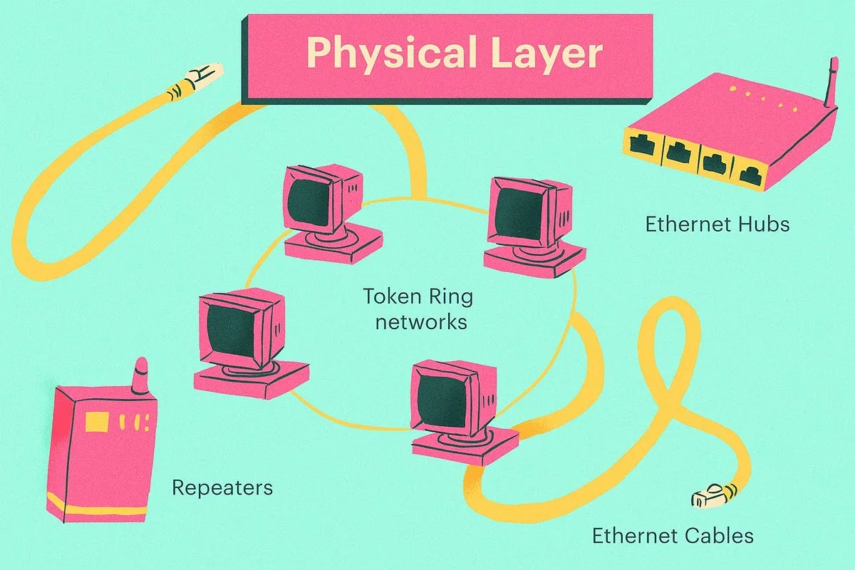
C. Physical topology: The Physical Layer (layer 1) is responsible for the physical connection between devices, and the topology of a network refers to the way in which devices are connected to each other. Here are a few examples of common network topologies used at the Physical Layer: bus, ring, star, hybrid and mesh.
D. Synchronizing bits: For two networked devices to successfully communicate at the physical layer, they must agree on when one bit stops and another bit starts. Specifically, the devices need a method to synchronize the bits. Two basic approaches to bit synchronization are asynchronous and synchronous synchronization:
- Asynchronous: Is a method of transmitting data in which a start bit and stop bit are added to the data to indicate the beginning and end of each data character. In asynchronous transmission, the sender and receiver do not need to use the same clock to transmit and receive the data, and the sender sends data as it becomes available, without waiting for a clock signal from the receiver.
- Synchronous: Is a method of transmitting data in which a clock signal is used to synchronize the sender and receiver. In synchronous transmission, the sender and receiver use the same clock to transmit and receive the data, and the sender sends data at regular intervals, determined by the clock signal. This allows the receiver to detect the start and end of each data character by using the clock signal, rather than using start and stop bits.
E. Bandwidth Usage: broadband and baseband are two fundamental approaches to bandwidth usage on a network.
- Baseband signaling: Is the method of transmitting a single digital or analog signal over a channel using the channel’s full bandwidth. Baseband is like having one person talk at a time on a phone call, the person can only say one thing at a time because they are using the whole phone line to talk.
- Broadband signaling: Is the method of transmitting multiple signals over a channel by modulating each signal onto a higher frequency carrier signal before it is transmitted. Broadband is like having a group of people talk on a conference call, all the people can talk at the same time because they are using a special way to share the phone line.
F. Multiplexing strategy: Is a technique that allows multiple signals to be transmitted over a single channel simultaneously. Is like having one big road that lots of cars can drive on at the same time. Imagine if all the cars had to drive on one lane, it would be very slow and only a few cars could drive at a time. But if we have more lanes, more cars can drive at the same time. This is what multiplexing does on a computer network, it makes sure that more information can be sent at the same time by dividing the road into different lanes.
There are different types of multiplexing, but the two main types are time-division multiplexing (TDM) and frequency-division multiplexing (FDM). Examples of devices defined by physical layer standards include hubs, repeaters, wireless access points, and network cabling.
Thanks for taking the time to learn about the Physical Layer of the OSI model! I hope you had fun learning about the different ways that data can be transmitted over a network, from the different topologies to the different types of signaling used.
Don’t forget to come back and visit my page to learn more about other exciting layers of the OSI model. With each new layer, you’ll be building a solid understanding of how networks work, and who knows, you might just become a networking pro in no time! See you later for the next lessons on Data Link Layer.
