welcome to the series on OSI Model and Encapsulation. I recently started a blog series “How to Get Started In Cybersecurity In 2023” as a I often get asked. So, I decided to do a four part series on that. Check it out here if you haven’t. The objective for today’s blog is to compare and contrast the layers of the Open System Interconnection Model (OSI) to better understand how data streams flow up and down within this model. I aim to explain this networking concept to you as if you were a 10 year old. Again, to be successful as a cybersecurity professional, your in-depth understanding of this concept will make you a valuable asset to you team. Let’s dig in!
The Foundation
The OSI (Open Systems Interconnection) model was developed by the International Organization for Standardization (ISO) in the late 1970s and early 1980s. It was first published in 1984 as ISO 7498, and it provides a framework for understanding how different layers of a computer network interact with each other. The OSI model is not a standard or protocol itself, but a reference model, it’s a way of thinking about and describing the interactions between different layers of a computer network. It is still widely used today and is a fundamental concept in the field of computer networking. This is fancy language for getting network “thingies” to communicate with each other, even if different companies made those network “thingies.”
The Purpose of Reference Models
One of the most common ways of categorizing the function of a network technology is to say at what layer (or layers) of the OSI model that technology runs. Understanding how that technology performs a certain function at a certain layer of the OSI model helps you determine whether one device is going to be able to communicate with another device, which might or might not be using a similar technology, at that layer of the OSI reference model.
Let’s take this scenario, so, you know how you have different rooms in your house, like your bedroom, living room, and kitchen? And each room has a specific job, like your bedroom is for sleeping, living room is for watching TV, and the kitchen is for cooking.
Well, computers also have different “rooms” called layers, and each layer has a specific job. These layers work together to help computers talk to each other and share information, just like how you and your friends talk to each other and share information.
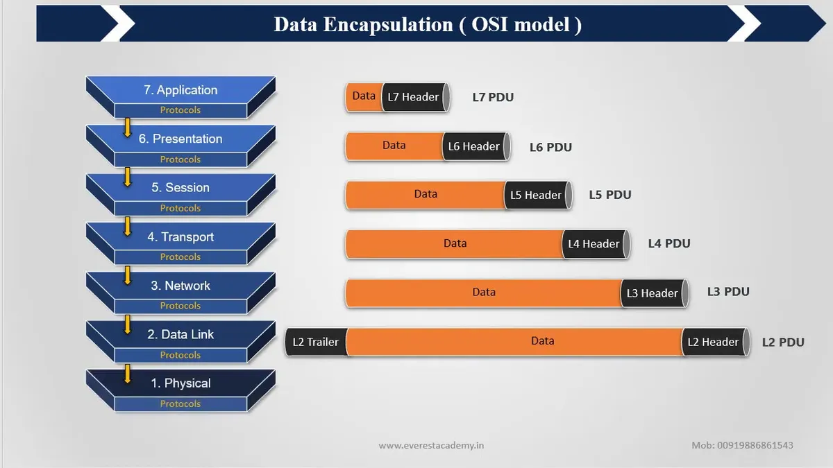
The OSI model is like a blueprint of all those layers, it helps us understand how the different layers of a computer talk to each other. There are 7 layers in total, starting from the bottom:
Physical Layer, it’s like the floors, walls and doors of your house, it’s where all the wires and cables connect.
Data Link Layer, it makes sure that the information sent from one computer gets to the right place on the other computer, like a postman delivering mail to your house.
Network Layer, it helps computers talk to each other, even if they are far away, like a phone call to your friend who lives in another city.
Transport Layer, it makes sure that information sent from one computer arrives in the right order, like a puzzle where you have to put the pieces in the right order.
Session Layer, it makes sure that the computers are talking to the right person, like knocking on the right door before entering a room.
Presentation Layer, it makes sure that the information is easy to understand, like a translator who can speak different languages.
Application Layer, it’s like the room where you use the computer, it’s where you open programs and do tasks.
Graphically, we depict these layers with Layer 1 at the bottom of the stack, as shown below:

At the physical layer, binary expressions (that is, a series of 1s and 0s) represent data. A binary expression is created using bits, where a bit is a single 1 or a single 0. At upper layers, however, bits are grouped together, into what is known as a protocol data unit (PDU) or a data service unit.
Let’s think of PDU as a package that we use to send something to our friends. Just like how you put a letter inside a box and put an address on it so it gets to your friend’s house, PDU is a package that we use to send information between different parts of a computer.
When we want to send information from one computer to another, it goes through different “rooms” in the computer, just like how a package goes through different rooms in a post office before it gets to your friend’s house. Each “room” is called a layer and each layer has a specific job, like checking if the information is correct, making sure it gets to the right place, etc.
The PDU is like the box we use to send the information, it’s not the information itself but it’s the package that holds the information and helps it get to the right place. Each layer has its own type of package, and we call it the PDU of that layer. It has special information on it, like the address of where it’s going, so that the information gets to the right place.
So, when data is sent from the Application Layer to the Transport Layer, it is packaged into a segment, which is the PDU of the Transport Layer. The segment then travels down the stack to the Network Layer, where it is packaged into a packet, the PDU of the Network Layer. The packet then travels down to the Data Link Layer, where it is packaged into a frame, the PDU of the Data Link Layer. Finally, the frame is sent to the Physical Layer, which sends the bits of data over the physical medium.
It’s important to note that the PDU is not the same as the data itself, it’s a container that holds the data and adds information necessary for the communication between layers.
In summary, PDU is a specific format for data used at each layer of the OSI model, it is the package used to carry data from one layer to another and contains information necessary for the communication between layers. In the next episode, we will discuss each layer and it’s specific function in great detail.
